(Comprehensive Guide to Power Rating Selection, System Architecture, and Short-Circuit Calculation)

With the rapid development of China’s “New Infrastructure” initiatives, data center construction has experienced explosive growth. As the fundamental backbone of big data and cloud computing, data centers demand extremely high power reliability and system continuity.
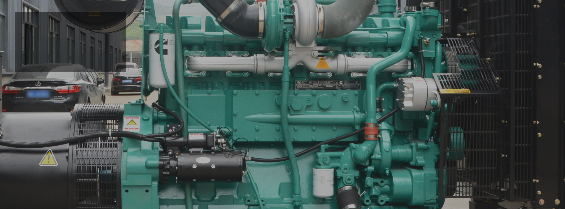
Diesel generator sets (gensets) serve as the long-duration standby power source in data centers. When the utility grid fails, gensets must start quickly, synchronize seamlessly, and carry the data center load from 0% to 100% in a short time. This places stringent requirements on:
Genset stability
Synchronization and load-sharing control
Dynamic performance
System architecture reliability
Although high-voltage (10kV) and low-voltage (380V) genset systems are widely used, many users still struggle with power selection, equipment configuration, and system calculations. This article provides a complete engineering guide covering:
Power rating types and selection methods
Common LV and HV system architectures in data centers
Short-circuit current calculation and equipment selection
Control systems and reliability considerations
According to GB/T 2820.1-2009, diesel generator power ratings are divided into four categories:
| Power Rating | Typical Meaning | Load Type | Operating Hours |
| COP – Continuous Power | 100% load continuous operation | Constant | Unlimited |
| PRP – Prime Power | Variable load | Variable | Unlimited |
| LTP – Limited-Time Power | Up to 500 hrs/year | Constant | ≤ 500 hrs/year |
| ESP – Emergency Standby Power | Backup for outages | Variable | ≤ 200 hrs/year |
Many users misunderstand the differences between PRP, COP, and ESP. Engines used in data centers often follow ISO ICXN standards, allowing 10% overload, which affects how PRP is interpreted in the communication industry (YD/T 502-2020).
YD/T 502-2020 selects COP, PRP, and LTP, but defines PRP differently:
PRP requires gensets to run continuously for 12 hours at rated power,
And to run 110% overload for 1 hour in every 12-hour cycle.
This overload capability differs from GB/T 2820.1 and is based on the engine’s ICXN overload allowance.
When determining genset power, engineers must consider:
Poor ventilation may reduce genset output by up to 30%.
This is common in soundproof rooms or incorrect acoustic design.
Unequal load distribution reduces total available capacity.
Data centers have high harmonic content. Generators must have sufficient:
Steady-state voltage regulation
Voltage dip tolerance
Harmonic withstand capacity
The debate between 380V low-voltage (LV) and 10kV high-voltage (HV) genset systems has existed for years. In practice:
There is no “best solution”—only the most suitable solution based on capacity, investment, reliability, and O&M conditions.
High reliability → switching point close to load
Short cable distance → minimal power loss
Lower maintenance requirements
Good for small–medium data centers (below ~6MW)
Current is very high → requires large cables
Cable routing & construction difficulty increases
Hard to parallel many gensets
Not suitable for large scale loads
Used in small data centers with simple structure.
(N+1 configuration may require shared generators or small parallel systems.)
Widely used in large data centers since ~2010.

Output current is 1/25 of LV systems
Cable quantity significantly reduced
Long transmission distance
Flexible room layout (generators can be far from server halls)
Easy to create a large capacity pool (many generators in parallel)
Higher maintenance & technical skill requirements
Centralized switching point (10kV bus) reduces reliability
Switching point further from critical load equipment (UPS)
Parallel generators feed into a 10kV bus with centralized ATS/AMF switching.
If the 10kV bus is under maintenance or testing:
One side of the transformer may lose power
Even with bus tie breakers, risks remain
Moving the switching point down to each transformer’s incoming feeder increases reliability, though cost is higher.
Even so, it is still not as close to the load as LV switching at UPS input.
Many engineers mistakenly select HV generator breakers and cables the same way as the utility side, resulting in oversized and costly installations.
Given:
Rated capacity: 2000 kW
Voltage: 10.5 kV
xdʺ = 0.108 (typical)
Base capacity Sj = 100 MVA
Using per-unit method:
Xdʺ = 0.108 × (100/2) = 5.4
Base current:
Ij = 100 / (1.732×10.5) = 5.5 kA
Generator terminal short-circuit current:
Ikʺ = 5.5 / 5.4 = 1.018 kA
Peak current ≈ 2.7 × Ikʺ = 2.74 kA
Because short-circuit current is low:
➡ 630A breaker is typically sufficient.
When 10 generators are paralleled:
Short-circuit current at a single feeder:
Ikʺ = 9 × 1.018 = 9.162 kA
➡ Breaker breaking capacity 20 kA is enough.
Using thermal stability formula:
Single machine:
Required Smin = 7.43 mm²
10-machine parallel short-circuit:
Required Smin = 66.88 mm²
➡ 70 mm² copper cable is sufficient
➡ If derating factors applied → 95 mm²
Engineering practice commonly uses 150 mm², resulting in unnecessary cost.
A stable generator system relies not only on hardware but also on its “nervous system”:
Parallel control system
Load management (kW, kVar sharing)
Fuel system control
Protection relays
Redundant power to all control devices (UPS-fed)
High reliability data centers particularly require uninterrupted control power for the entire generator control system.
This article provides a full engineering analysis for diesel generator system applications in modern data centers:
Clarifies key power rating definitions and selection methods
Explains the strengths and weaknesses of HV and LV generator architectures
Offers real engineering examples for short-circuit calculation and breaker/cable selection
Highlights the importance of generator control systems in overall reliability
By following proper design principles, engineers can:
Improve supply reliability
Avoid oversized equipment and unnecessary investment
Ensure diesel gensets fully meet data center requirements


Tel : +86-591-86397381
Email : sale@hosempower.com
Whatsapp :+8613205904365
Address : C2 Building, Cangshan Wanda Plaza, No. 216 Pushang Road, Fuzhou City, Fujian, China.
Copyright © 2026 Fuzhou Hosem Power Co., Ltd. All Rights Reserved
 IPv6 network supported